Tuesday, January 22, 2013

First scale test results

I took some time to analyze the results from my scale test.  If you like graphs, then keep reading.  If you don't like graphs then skip to my conclusion at the bottom.  I happen to like graphs...

To summarize the previous post, I wanted to see if there were two effects happening to my fancy new RS232 scale: 1) temperature and 2) sensor drift (or creep).  The easiest way to track this was to measure the weight of an object with a constant mass over time, while also measuring temperature over the same time span.  I did that and now have a week's worth of measurement data to sift through.

Figure 1: Temperature and Weight vs. Time
First I graphed weight and temperature each versus time.  Figure 1 shows this graph.  You can immediately see that the measured weight correlates closely with the temperature, so clearly I was right that there is a temperature effect.  The second thing to note is that the weight line shows clear quantization, but this is to be expected as the scale only specifies to have a 0.1 lb resolution (but it's still nice to see it clearly in the graph).  Another thing to note is that the temperature is pretty noisy.
Figure 2: Average Temperature and Weight vs. Time
Figure 2 is the same graph but with a moving averaged temperature.  Perhaps a "moving average" is not the correct term for this; I never did much with formal statistics.  I basically just calculated each reading by taking the mean of the previous 6 readings.  You can see the temperature line looks much less noisy now and the correlation between temperature and weight still remains.

Figure 3
My next task was to try and figure out the mathematical relationship between weight and temperature, so that I can then (hopefully) correct for temperature and get a more accurate weight reading.  The graph for weight versus temperature is shown in Figure 3.  There are several interesting things here.  The first is that you can see that both the weight and the temperature are quantized since all the blue points in the graph come out on grid lines.  The next thing to note is that the point cloud is pretty widely distributed (which isn't good).  I had Excel generate a best fit linear trend line.
Figure 4
Next up I repeated that graph (Figure 4) but with the the averaged temperature data from Figure 2.  Now you can see that the quantization in the temperature data has disappeared but remains for the weight, which is what we'd expect.  The trend line has changed a little based on this adjustment.  I also threw a 6th order polynomial fit trend line on the data to see if that would fit the data better, but as you can see that is nearly a straight line, so we'll stick with the linear fit line for future calculations since it seems to be a pretty good approximation (at least compared with a polynomial fit).
Figure 5
Now from this we can use the calculated trend line to create a mathematical attempt at canceling out the temperature effect of the scale readings.  Figure 5 is a graph of the temperature-adjusted weight plotted over time.  The ideal line would be a line that is constant at 55 lb.  The adjusted weight line is clearly not a straight line but if you compare it to Figure 2 we have certainly made an improvement over the raw weight readings.

As it stands this temperature correction is probably useful enough that I could start using the scale for continuous weight measurements, however I'd like to make it better if I can.  I think one improvement I can make (which I mentioned in my previous post) was that my temperature sensor has pretty low resolution (about 1 degree Fahrenheit). I suspect that having a sensor with 0.1 degree resolution would help, and might bring the point cloud in Figure 3 into a tighter cloud which would make the generated trend line more accurate.  So now I'm going to start looking around for a more suitable temperature sensor (I might already have one on hand in my parts library) and re-run the test to gather fresh data.

Zeo sleep monitor


My wife got me a new toy for Christmas this year, a Zeo Sleep Monitor. It's a device that fits on your forehead while you sleep and measures your brain waves while you sleep. Based on your brain waves it logs what phase of sleep you're in (light, REM, deep, or awake). I got some time to try it out a few nights ago and I was pretty impressed!

Above, you can see a screenshot from the app on my phone. You can see for yourself what each of the colors means on the graph above.  The fun thing to note for me is that it lines up perfectly with what happened that night.  At around 1AM (the second set of red lines) my dog woke me up to be let outside.  Then around 2AM my wife woke up which woke me up for a little while.  Then at around 6:30AM my wife woke up to get ready for work which again woke me up.  So that correlates the data with reality nicely.

The interesting things in the graph are what I wouldn't ordinarily be able to determine for myself, namely differentiating between light sleep, deep sleep, and REM sleep.  I find this pretty fascinating.  I think this also means that I don't have sleep apnea (or at least not this night), since I would assume there would be many more red lines throughout the night.

I'm going to keep using this as much as possible for the next few weeks to get an idea of what my sleep habits look like over time.  The Zeo Android app also has another feature whereby you can set an alarm and the app will try to wake you when you're in an optimal sleep state.  This works on the theory that you feel better and more alert if you're awakened when you're in a light sleep state.  I haven't tried that feature yet, but I will soon.

When I find some time I'd like to find a way to use the Zeo sensor to monitor my sleep cycles and when I'm in a REM sleep cycle trigger subtle lights or sounds that might allow me to experience lucid dreaming.  I found this Android API which may aid me in doing that.

Update: I tried the alarm feature last night and it is amazing!  It delayed my wakeup time by about 15 minutes to wait for the REM cycle I was in to end.  I woke up feeling fantastic!  I may have to start using it every night.

Wednesday, January 09, 2013

Testing an RS232 scale

To further the experiments I've been doing with measuring specific gravity, I needed to take long-term continuous weight measurements (5-10 days total). I started searching for a scale or load cell that would be appropriate.
My specific use case involves monitoring the weight of an object in the range of 50-70 lbs for 2 weeks.  Since we have a heavy weight on the scale for a long time a problem that could come up is sensor drift (also sometimes called creep).  This effect is similar to what happens if you hang an object from a suspended spring.  Over time the spring will slowly deform.  The rate of the deformation depends on many factors like the weight of the object and the physical properties of the spring.  The same thing happens with a scale.  Although mechanically different from a suspended spring, in many other ways it's very much like a spring.

Another factor that can throw off the readings from a scale is temperature.  As the temperature changes the properties of the components in the scale also change.  If these changes aren't compensated for in some fashion then they will affect the scale's readings.

I initially tried to measure a 55 lb test weight using a 75 lb maximum capacity digital scale.  Within minutes the scale's readings started drifting.  I assumed that this was probably due to creep and was probably so prominent because I was weighing something close to the rated capacity of the scale.  This scale also had the additional failing that it did not have a way to communicate externally (which as you'll see soon was an important requirement) so I decided to look for a different scale.

I reasoned that if I found a scale that had a maximum capacity that was significantly larger than object I was weighing, then it might not display significant effect from creep (or at least for the 2 week period that I needed continuous readings).


Luckily I found a 300 lb capacity shipping scale (MyWeigh HD-300), and a well-written tutorial from Adafruit.  This scale was a little more expensive than what I had in mind, but it's worth the price considering all of its features:
  • 300 lb capacity
  • RS232 communication
  • ability to disable auto-off (most scales turn off automatically which sucks for continuous measurements)
I quickly started an "eyeball" test by again placing my 55 lb weight on the new scale.  I kept a log book near the scale and roughly every 60 minutes I would write down the time and the displayed weight.  I left this experiment running for about 4 days.  I should note that I didn't stick to the 60 minute test interval that closely.  Sometimes I would leave several hours between readings, sometimes it was more like 30 minutes, and I didn't wake up to take readings in the middle of the night; I like science but I like sleep more.

The results of this test told me that something was causing the displayed weight to vary by about 1 lb over the course of 4 days.  I had a suspicion that temperature was causing much of the variation (the weight would be lower when it was cooler in my house and higher when the temperature was higher).  I couldn't really tell if there was any effect from sensor creep.

Next I decided to repeat the above experiment but make it a little more scientific.  For this run I wanted to run for at least 10 days and gather temperature and weight readings every 10 minutes.  Of course, this is exactly what computers are made for.

The test set up consists of a python script running on an old laptop.  The script communicates with the scale via its RS232 interface to gather weight readings.  To get the temperature I decided to use an Analog Devices TMP36 sensor that I already had on hand.  Coincidentally, Adafruit had another tutorial on using this sensor with an Arduino.  I used some of the ideas from the tutorial but wrote my own Arduino firmware to make it act as a serial thermometer.

The test script on the laptop was modified to also query the Arduino for the temperature and log the returned value along with the measured weight value to a file every ten minutes.  

The test setup from left to right: laptop power supply, USB wifi dongle, scale control box, laptop, plywood to act as stable platform for scale, Arduino with TMP36 sensor, MyWeigh HD-300 scale with 55 lb test weights
I put the source code for the python test script and the Arduino firmware on github.  Keep in mind that the script was written to run on Windows and would need to be ported to run on another operating system.  Also, since I implemented the script very quickly I didn't spend much time or effort on error checking so it's not very robust in that respect.  You have been warned.


At this point you may be wondering why I didn't just use the Arduino by itself to do the data logging.  I have a few reason for that:
  • I needed a circuit to convert the RS232 voltage levels of the scale to TTL voltages that the Arduino can understand.  I already had the hardware to do that but I didn't want to waste time assembling it when I had a laptop with a perfectly good RS232 port available.
  • I didn't have an Real-Time clock to keep track of time or anything to use for large data storage (SD card socket).  The Adafruit data logging shield would have been ideal for this but I didn't want to wait to run the test.
After I was half way through implementing the test I realized that the TMP36 sensor used in combination with the Arduino's 10-bit resolution ADC only gives a resolution of about 1 degree Fahrenheit.  I would have preferred to have 0.1 degree of resolution but decided to run the experiment anyway and see how the numbers looked.

I'll create an additional post with the results from the first test run.

Improved Security Node

I've spent some time recently polishing the Security Node demo I made a while back to the point where it is no longer a demo.  It's now installed and functioning in my house.

Here are some of the changes:

  • Integrated catisith2's keypad interface code
  • Added logic so alarm system is run completely by the JeeNode
  • Replicated original functionality of the DSC alarm control board
  • Added circuit to control the (very loud) siren
  • Send radio packets when events occur (alarm, arm, disarm, doors open/close)
  • Handle remote commands via radio (mainly arm/disarm commands)
  • Made a small "cheatsheet" with all the commands to attach inside the keypad panel

I've update the source code in my github repo.

I'm pretty satisfied with how the Security Node turned out but I have some things I'd like to change:

  1. The alarm system runs fine locally but my ultimate goal is to have an external interface so I can receive texts when events occur and remotely arm/disarm the system.  I'm still trying to figure out how I want to do that.  JC Wippler is doing some interesting research along these lines.
  2. There isn't much security with the arm/disarm radio messages, though I could encrypt the radio traffic pretty easily.
  3. The final board works well but it looks ugly.  I'd like to redraw everything in EagleCAD and have a proper PCB made.
  4. Adding a battery backup so the alarm will still work when there is a power outage.
Here are some pictures:

Security Node without JeeNode installed

Security Node installed

Keypad communicating with JeeNode


Tuesday, January 08, 2013

Beer Crate

Over the holidays, I set out to build some more permanent storage cases for my homebrew beer.  I had just been using whatever cardboard beer boxes I could get my hands on.  Now that I'm getting more into homebrewing I thought it would be nice to put my woodworking skills to good use.

The finished beer crate
Design
Design decisions:
  • Be easily stackable (up to 3 or 4 high)
  • Some sort of locking/registration mechanism so when they're stacked they stay stacked
  • Separators between bottles so the bottles don't knock together when moved
  • Sturdy!
  • Some method of identifying what beer is in a given case
  • Hold at least 12 bottles (24 seems like too much)
  • Tall enough to hold any normal 12 ounce beer bottle
  • Handles for ease of carrying
I started by measuring a cardboard beer box to get some general size guidelines.  I also measured the tallest 12 ounce beer bottle I could find to see what the height needed to be.

Based on the measurements I designed the beer crate in Sketchup (as usual).  I decided to use 3/4 inch pine boards for the sides and end pieces and 1/8 inch hardboard for the bottom and the separator pieces.  There are two interesting features: The first is that I plan on applying chalkboard paint to the sides of the crate so I can write info on the batch in chalk.  The second interesting feature is a trick I learned from woodgears.ca.  The idea is to use marbles to "lock two flat surfaces together in a removable fashion.  The idea is to drill two hols on the two surfaces just wide enough and deep enough to fit a marble.  The marble then sits above the surface of the top edge end piece and fits into a matching hole on the bottom of the end piece.  In this way the crates can be stacked without worrying about them slipping.  Since the marble is spherical it's easier to line up than a cylindrical peg.


The beer crate design in Sketchup
Construction
The construction details are not that interesting since they are just standard woodworking techniques.  The sides, ends, bottom, and separator pieces were cut to size from pine boards and hardboard sheets.  A slot was cut into the sides and end pieces to fit the bottom piece similar to the way drawer bottoms are traditionally made.  

The hand holds were cut in the end pieces with a forstner bit and a jigsaw, and sanded smooth using an oscillating spindle sander.  The recesses for the marbles were drilled using a drill press and a template I made  to make sure the holes line up properly.
Slots were cut halfway through the separator pieces so that they would fit together.  To make these cuts I used my table saw and just stacked up several separators at a time and pushed them into the saw blade until the blade hit a pencil mark half way through the separator.  There are cleaner ways to make this cut but since the cut is not visible after the seperators are assembled, I wasn't too concerned with cosmetics.  If you'd like to see how these separators work just take a look at a carboard 12 pack box and they go together the same way; they're just made of hardboard instead of cardboard.

I just used a butt joint to connect the side and end pieces.  I put 1.25" wood screws into countersunk pilot holes to hold it.

Finish
I first sanded all the pine pieces mainly to get rid of machine marks.

I used two coats of clear gloss wipe-on polyurethane to seal the side and end pieces.  I didn't put any stain on the wood because I like the look of unstained pine.  I left the outside face of the side pieces unsealed since I wanted to apply the chalkboard paint there.

For the chalkboard surfaces, I first primed with some white latex paint that I had lying around.  After that had dried I sanded lightly and applied one thick coat of black Rustoleum chalkboard paint using a foam brush.  After it had dried it didn't seem to need a second coat so I left it at that.

Future Improvements
This was the first project that didn't require me to make some adjustments to the design during construction.  I credit using Sketchup and doing careful measurements before I started.

Now that I've finished the prototype I need to make 8 or 9 more to hold all of my homebrew beer.  I'm really looking forward to doing some "assembly line" style woodworking.  It seems like 90% of the time in woodworking is spent setting up for each cut, so making 10 of something doesn't take 10x more time than making 1.  I usually only make 1 of a project so it will be fun to make many more.

Even though this project went well I have some concerns and improvements for the future:
  1. I might want to use some nicer wood like oak in the future.  Then again the pine looks pretty good and has the additional advantage of being cheap.
  2. The butt joint isn't that pretty; using dovetails or finger joints would look better.
  3. I'm a little worried that the placement of the marbles may be a little too precise and I might have trouble getting things to line up when I have multiple beer crates.  I can probably get around this by only using two marbles placed above each handle instead of the current 4 marble design.  Also I could make a jig to align the pieces when I drill the pilot holes for the screws.  The jig would ensure that I get the distance between the end pieces exactly the same every time.


Monday, December 31, 2012

Updated desk plans

Recently I discovered woodgears.ca and was inspired by Matthias Wandel's amazing Sketchup plans.  He sells some of the more complicated ones (and I think they are well worth the price) and offers others for free on his website.  The great part of his plans is that not only are they 3D models of the project, but by utilizing the features of Sketchup they are also excellent instructions for constructing the project.

I did a little analysis of one of his plans to try and figure out how he does it.  I found that he uses three important features of Sketchup to create his plans:

  1. Components: Componentizing pieces of a model makes it easy to organize the model but also much simpler to highlight specific parts of the model.  Matthias seems to organize components based on how things are organized in the real world.  For example, a table leg or drawer would each be a component.
  2. Scenes: In Sketchup it's easy to record a given camera viewpoint (among other properties), and this is called a scene.  Matthias' plans use scenes to hide various parts of the model and highlight individual construction or assembly steps.
  3. Layers: These are used to add text and dimensions that would clutter the model if they were all visible at once.  The hidden or visible nature of a layer can be recorded as a property of a scene.

I already knew the basics of using Sketchup but I decided to try out some of Matthias' techniques to improve an existing model that I created for the writing desk I built for my wife.  I already had a completed model, so I set out to organize the model as a series of components and add scenes and layers to illustrate the construction process.

I'm really happy with the results although it took me many hours to complete the new Sketchup model. I would like to do this for my arcade as well, though that would take far longer to complete.

I still haven't found a way to host the Sketchup file (at least not a way that I like), but in the meantime I exported a video of the various scenes from Sketchup.  The resolution doesn't really do it justice and for some reason the YouTube import cut a few frames here and there which makes the video stutter, but at least it will give you an idea of what it looks like.


Sunday, December 23, 2012

Turning an arm lamp into a camera mount

I want to dabble with making some videos of some of my projects, but I don't have much in the way of video equipment.  I do have a decent point-and-shoot camera which can take video, but I don't have a tripod or anything decent to hold the camera.

Since I don't want to invest much money in this endeavor at first, I started thinking about things I could use that I already had that might work.  I have a really old arm lamp from my college days that was in sad shape but still had a decent arm.  The lamp part of it was messed up; I replaced a broken switch on the top of the lamp with a slide switch and tried to insulate it with electrical tape.  Eventually the electrical tape came off and I shocked myself many times while trying to turn on the lamp in the dark.  Here's how I turned it into a camera arm.
An old arm lamp.  Note the sketchy soldered on switch on the top of the lamp shade.

The first step was to remove the lamp.  The lamp shade was attached to the arm via two rivets.  I drilled through those easily enough and the lamp came free.  Next, the lamp cord was threaded through the hollow parts of the arm so I pulled the cord out.  That left me with just the bare arm itself.

The arm lamp minus the lamp parts.

The next problem was that the mounting plate that had previously been riveted to the lamp shade was curved and I needed it to be flat to allow mounting a camera platform.  I used a large C clamp to squeeze the plate into shape.  This worked surprisingly well and only took a few minutes.

Flattening the mounting plate.

I knew there was usually a screw hole in the bottom of most cameras and after a bit of googling it looks like most of the screw holes are 1/4"-20.  I had several bolts available of the right size and ended up choosing one that was about 1.5 inches in length and with thumb knurls so I could grip it without tools. My next worry was that I didn't want to damage the camera  by bottoming out the bolt in the screw hole by screwing it in too far.  To address this I got a wing nut to use to tighten the bolt to the bottom of the camera mount.

To mount a camera you put the camera on the top of the mount plate and screw the bolt in a few turns through the mounting hole.  Next tighten the wing nut up to the bottom of the camera mount plate until the camera is secure.  You can see how this looks in the picture below.

The first camera mount plate.

The final camera mount with bubble level attached.  Note that the wing nut in this photo is mounted on the other side of the mount plate when there is a camera attached.

The camera mount plate is pretty simple.  I went through two iterations before I got it the way I wanted.  It consists of a block of scrap wood with a few pilot holes drilled for the arm mount plate, and a larger hole for the bolt to pass through.

I thought it would be nice to put a bubble level on the camera platform to aid in leveling the camera.  I found a bubble level at Lowe's like these for a few bucks.  The ones I got had plastic hooks on each end so that they could hang from a string.  I cut off the excess plastic from the level and hot glued it to the side of the camera mount platform, taking care to make sure it was parallel with the surface that the camera would rest on.

The arm mounted on a stool with a camera attached.

The whole project took less than an hour and about $2 for the bubble level.  I already had the lamp on hand but if I hadn't I probably would have gotten this one from IKEA for another $9.  I'll be running the camera arm through its paces in the coming weeks, and if things go well you may start seeing project videos on this blog.

Saturday, December 22, 2012

Fridge Repair

A couple of years ago the water dispenser in my refrigerator started leaking.  At the same time I also found that ice was plugging up the chute that allows water into the ice maker; whenever water was dispensed into the ice maker it would hit the ice plug in the chute and shoot water all over the freezer.  So that was fun.

After a bit of quality time spent with Lady Internet, I found that these symptoms point to a bad solenoid valve where the water comes into the fridge.  Basically, the solenoid slowly goes bad which lets a small amount of water leak out of the water dispenser and into the freezer compartment which slowly freezes and plugs up the water inlet to the ice maker.

So I jumped on my favorite appliance parts website Appliance Parts Pros, and ordered this part.

This part was pretty cool in that it came with an info sheet from the manufacturer that showed exactly how to install it.  That was a pleasant surprise since usually you're left to your own devices in figuring out how to replace the part.

I got it installed in about 30 minutes and then my water dispenser started working again.  I still had to remove the ice maker and thaw out all of the ice that had accumulated everywhere, but after some work chipping away the ice and re-installing the ice maker I had that working too.

I also came away from this really impressed with the design of ice makers.  They're compact and efficient and are really ingenious.  Here's an article that talks about how they work (almost all ice makers use the same design).  The article also has a really cool animation that shows how it works graphically.

Closeup of the old solenoid valve

Aren't these awkward angles great? This is the bottom back corner of the fridge where the water solenoid lives

Friday, December 21, 2012

Washing Machine Repair

Not long ago my washing machine stopped working.  When I pressed any buttons on the control panel it would just beep at me and do nothing.

After some internet research I came across a service manual for my model of washing machine, a Whirlpool Calypso.  The manual had a nice troubleshooting guide showed me how to check the control panel with a multimeter to see if there was a button out.  The manual also showed how to get access to the control panel (shove a putty knife in the crevice where the control panel meets the body of the washing machine and pop the spring clips).

I ohmed out the control panel according the to the service manual and sure enough it was bad.  I ordered a new one from Appliance Parts Pros. It was kind of expensive, but much cheaper than a new washer so I decided to roll the dice and order it.

The service manual was really good about having procedures for testing things and had procedures for replacing many components like the control boards and motors and things but it didn't have a procedure for replacing the control panel.  

The hardest part was removing the old panel.  First I had to wrestle witht he plastic end caps that bookend the control panel.  Then I found that the bar which holds up the circuit boards you can see in the picture below was glued to the back of the control panel.  I pulled out my trusty putty knife again and used it to pry the control panel free.  Luckily it wasn't very strong glue and it came free pretty easily once I got it started with the putty knife.

Once I had the old panel removed putting the new one in was as simple as putting the end caps back on, connecting a ribbon cable to the control board, and reversing the rest of the disassembly.

And luckily the washing machine started working again as soon as I re-connected power.

The inside of the control panel after a bit of disassembly

Back side of the new display panel

Good as new

Droid Incredible Repair


A few months ago the screen on my wife's Droid Incredible got cracked.  Rather than invest in a new phone I decided I'd try and replace the touchscreen with something like this.  I watched a YouTube video on how to do it here and jumped in.

I was nervous as hell while I did it; it really felt like I was performing surgery.  In the end I was successful and saved a bundle of money in the process.

Here's some tips I learned that seemed to help:
  1. Use a hair dryer to heat up the adhesive that attaches the touchscreen glass to the phone's frame.  It helps it peel off much more easily.
  2. Use powder-less rubber gloves when handling the screen since this will help avoid getting fingerprints between the touchscreen and the LCD where you can't clean them off after reassembling the phone.
  3. Work on a clean flat table and have some container to put all the tiny screws and other parts so they don't roll away and get lost.
  4. Take your time.


Udacity: Web Application Engineering

I was pretty excited when Udacity was introduced.  It seems like a really great idea for democratizing education (though they were't the first to come up with these ideas).

I decided to take the course they offered on Web Application Engineering.  I had two goals: 1) Try out the Udacity education model and 2) Gain knowledge in web apps for help with automating my house.  

Overall I was very impressed with the course.  I took the first offering of the course and even with it being the first time they had done the course it went very smoothly.  They got Steve Huffman (of Redit and Hipmunk fame) to teach the class which was pretty impressive since it's someone that has put together a successful real-world website.

The course was 7 weeks long.  Each week there was a lecture with interactive questions interspersed every few minutes to check for understanding.  The lectures were recorded so you could do them anytime they were convenient.

Each week there was also a homework which reinforced the concepts from the lecture.  For the Web Applications course used the Google App Engine for development which worked pretty well and was a good way to make web app hosting available to large numbers of students.  We also use the python version of the Google App Engine which was nice since I really like python.

They didn't enforce that the homeworks be done in the week they were given but I'd highly recommend that you do them that way since the lectures and homeworks can really pile up otherwise.  In this way, it was like a normal college engineering course.  On average each week took me about 4 hours or so.  The homeworks were actually tested in an automated fashion by having a standard web interface for each one.  This really gave incentive for getting everything to work; if they hasn't graded the homework I would have been tempted to just say "Bah, I understand, no need to do the homework...".

At the end of the course there was a final project which was a wiki style webpage from scratch.  It required integrating everything you'd learned in the course and was a really nice way to wrap everything up.

Overall the course was very well done and I would take another course on Udacity without hesitation.  This gives me hope for the future of education.

Custom tools made from wood

Recently I was trying to debug my dishwasher.  It was leaving crusty deposits of food particles and leftover detergent on all the glasses.  It was pretty nasty.

I wanted to eliminate the possibility that there were just some leftover bits in the dishwasher that kept getting re-deposited on the dishes, so I took apart as much of the dishwasher as possible to clean out all the nooks and crannies.

When I got to the spray arm I was able to unscrew the whole thing by twisting the bottom post counter-clockwise.  But this took the entire spray arm assembly loose and I couldn't really get to the inside of the arm where I could see there was plenty of caked-on dishwasher detergent.  I'll spare you pictures of the gunk since it's kind of gross.

I noticed that the central top portion of the spray arm looked like it should detach but there was nothing that would allow me to grip it except for 4 small plastic posts.  I knew if I tried to grip these with pliers or something I would just shred the plastic and ruin it.

So I thought I might be able to fashion something that would act as a custom wrench of sorts.  I decided to try it with wood since I have lots of scrap wood available and the tools to work it.

I started by putting some blue chalk dust on the ends of each of the 4 plastic posts, then I pressed a chunk of 2x4 against the posts to transfer the marks.  Then I went to the drill press and drilled holes where the chalk marks were on the 2x4.  I noticed that there's a raised area in the middle so I used a forstner bit to drill out a recess in the 2x4 to fit.

I then tried it and it slid right over the posts and with a small clockwise twist the central part of the spray arm lifted free.  Pictures of all of this are below.

So it goes to show if you're resourceful you can fashion your own custom tools, even if all you have available is an ugly chunk of wood.

Dishwasher spray arm.  Note the 4 plastic posts on the central portion.  That's what we'll use to turn the  center part.

Here's the "wrench" after machining the holes in the correct locations.

The "wrench" fits right on top

After turning the tool about half a turn clockwise the center portion detaches from the spray arm!


Wednesday, September 05, 2012

Reverse engineering a security keypad

When I previously did the reverse engineering work on my home security system, I just skipped trying to get the keypad working.

Since then someone posted some code to interface an arduino to the exact model of keypad I have in my house (a DSC PC1500RK).

This weekend I tried the code out and it worked perfectly!  Thank you caitsith2, who ever you are!

Now I just need to integrate this with my security node...

Thursday, July 12, 2012

Security Node demo

I created a demo recently to show off the security node I've been working on implementing using JeeNodes. This is not the final version (though the hardware is pretty close to final), eventually I want to use something like HouseAgent to control the entire system.

This was based on my work in reverse-engineering my security system.

Hardware
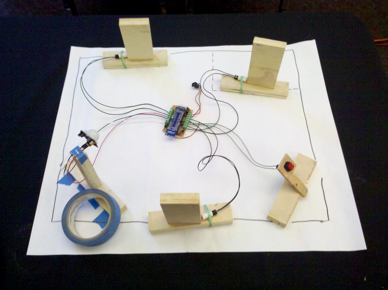
Very rough model of my house with simulated doors, panic button, and motion sensor.  The JeeNode is in the center.
The hardware consists of a JeeNode attached to 3 magnetic door sensors, a push button, a temperature sensor, and a motion sensor (with controllable power).  I built the circuit on protoboard since it is a one-off project and the circuit is pretty simple.  It attaches to the JeeNode via the standard port connectors, so it's a little like an arduino shield but with the JeeNode layout.

I decided to use this project as an excuse to try out Fritzing.  I primarily wanted to try this since I thought it might be a decent tool to use to lay out the components on the protoboard, since I usually use EagleCAD but it doesn't allow you to work with protoboard.  The breadboard view in Fritzing worked well for this but I still think I could have done it more quickly with pencil and paper.  But at least now I have a decent (if messy) electronic version.

The interface is simple.  The switches are wired directly to the digital inputs of the various JeeNode ports (also using some of the unused analog inputs as digital inputs).  I use the ATMega328's internal pull-up resistors to save some components in the schematic.  I used a 7805 voltage regulator to bring the 12 volt supply's voltage down to something more reasonable for the JeeNode.  The 5V is regulated further to 3.3V by the JeeNode's on-board regulator.


I added a couple of transistors to the circuit to control power to the motion sensor and siren which both use 12 volts.  I also inserted a switch in the siren circuit so there's a hardware way to turn the siren off just in case there is a software failure (the siren is REALLY loud).  While I'm testing things out I'll probably only have the siren circuit enabled while I'm home so I can monitor things.

Firmware
The firmware is pretty simple and has lots of room for improvement.  It should be noted that I haven't done any work to improve the power usage of the firmware since this node will be wall-powered (the motion sensor and siren require way too much power to be battery powered).  The sketch polls all of the inputs every 2 seconds and sends out a packet with the sensor readings.  It also checks for received packets that contain one of two commands: to power up/down the motion sensor or to turn on/off the siren.

In the near future I will probably make this sketch event-based; it will only send sensor packets when one of the inputs changes value (or once when the node first powers up.  I'll also probably make it handle a 3rd command to poll all of the inputs and return a packet with the data (force an event).  Since this node will always be wall-powered I probably won't bother with using the power management functions available in JeeLib.

Host Software
I wrote the host software in LabVIEW.  This is a prototype and will eventually be re-written to be a web-based interface (perhaps using HouseAgent).  The VI monitors the serial port for messages from a gateway JeeNode running the standard RF12demo sketch.  It then parses these messages and extracts the sensor value from them.  Based on pressing buttons on the front panel the VI will also send messages to the node to turn on power to the motion sensor; it then starts a timeout to allow the motion sensor time to initialize after power up.

I used Sketchup to create a quick, not-to-scale, 3D floor plan of the first floor of my house.  I think it spruces up the front panel nicely.


Screenshot of the host-side UI


The host including the host-side JeeNode connected via USB


Tuesday, July 03, 2012

Reverse Engineering my Home Security System

I've been reverse engineering the security system that came installed with my house.  My ultimate goal is to re-use some of the sensors for my own home automation project while bypassing the old control board.

A bit of theory

The system works by monitoring multiple "zones" (up to 6 for the system in my house).  Each zone is really just a digital input that has a switch wired to it that can be open or closed. The control board can be configured on what state constitutes an alarm (for instance, a closed switch on Zone 1 means that the front door is open).  There is a bit more optional complexity that can be added to each zone as well.

The first complexity is that multiple sensors can be added in the loop that the controller monitors.  A good example of this is that you could put several monitored windows one a single zone by wiring the switches in series with one another in such a way that if any of them opened then the whole circuit would open; this would be like wiring the window states into an logical OR gate.  Note that this would also work even if the window switches were normally open (NO) switches, but in that case you would wire the sensors in parallel, such that normally the whole loop would be open but when a window opened one of the switches would close and the controller could detect that state.
Control loop for multiple Normally Closed (NC) sensors 

Control loop for  multiple Normally Open (NO) sensors

Another complexity is that you can use what are called end of line (EOL) resistors in the zone loops.  The idea of these resistors is to provide a third state to the loop besides open or short circuit.  By having a third value on the loop and using that as the nominal value you can detect when a fault condition occurs (either short circuit or open circuit).  The controller can be configured to handle EOL resistors (whether to use 2 or 3 states for a given loop).  In the example below the zone loop should normally read a resistance of R, but when one of the sensors opens then it should read an open circuit.  If the loop reads as shorted then we know that something is wrong with the loop.

Control loop for NC sensors with EOL resistor

Typically all of these sensors will be hard-wired from where the thing they are monitoring actually is.  For instance, if you might have a magnetic reed switch embedded in your front door frame which is wired back to your central control box.  Depending on how the sensor was installed, the wires will be run through the walls, under carpeting, or under the base boards against the wall.

Deciphering my system

My security system is a DSC PC1550 with a DSC 1500RK keypad.  I found an installer's manual online which helped a bit in deciphering things, but mostly I learned quite a bit from looking at the diagram on the inside of the control box (pictured below).  It appears like all of the sensors are connected to the main control board via a screw terminal block

By inspecting what was wired and examining door frames for the tell-tale plastic circles that indicate a magnetic door sensor, I determined that I had 3 door sensors, a motion sensor, a panic button, and a siren.

I started off by checking the resistance of each zone loop with my multimeter.  The motion sensor has to be powered so I supplied 12 volts to it and it worked like a charm.  The panic button also worked.  I hooked up 12 volts to the siren and it worked too.

When I tried the door sensors all of them registered as open circuits regardless of the position of the door.  I started troubleshooting: I pulled  one of the door sensor out of its whole and checked that it did indeed close the switch when a magnet was near, and I checked that all of the magnet and switches were close enough that the switch should trigger when the door was closed.  After that I started pulling up carpet to find the wires that were run under the carpet, and eventually I determined that the wires were accidentally cut during installation of new carpet.

I tracked down all 4 of these wire breaks (that's right, one of the door channels actually had two breaks in it) and fixed them, which involved prying up lots of carpet in my living room.  But eventually I got all of the door sensors working again.

And the good news is that all of these sensors act as switches and should be easy to interface to my own security monitoring hardware.  The only thing I haven't reverse engineered yet is the DSC 1500RK keypad.  I wasn't able to find solid information on the serial protocol it uses, so I'll leave that for later.  My plan is to eventually have my entire house controlled via my smart phone, so I don't care that much if the wall-mounted keypad works or not.

The diagram on the inside of my security control box

Monday, July 02, 2012

Appliance Repair

At least once a year, I have some kind of appliance break-down: my refrigerator stopped chilling food, washing machine electronics went bad, dishwasher started leaking, icemaker stopped making ice – the list goes on and on. Against my wife’s better judgment, I decided to try and fix these problems myself.
I like the idea of repairing things rather than throwing them out and getting new ones. There are so many benefits, including:
  • Saving money by not hiring a repair person and even more money by skipping out on buying a new appliance
  • Feeling a big sense of accomplishment when you can find and fix a problem yourself
  • Having a great excuse to take something apart and figure out how it works
  • Helping the planet by keeping old appliances out of a landfill

6 General Tips for Repairing Appliances

1. Reader’s Digest Fix It Yourself manual

This book is a great resource for troubleshooting and repairing everything in your house including appliances. I received this as a gift years ago, and it has saved me hundreds of dollars in repair costs. The sections on individual appliances are short and sometimes lack the depth required for a complete fix, but they usually have excellent diagrams and troubleshooting guides. I often go to this book first for troubleshooting appliance problems.

2. Learn to use a multimeter

A multimeter is an inexpensive tool that can measure voltages and resistances (and sometimes other electrical properties). You should be able to find a decent one for $10-20. Make sure that it measures AC and DC voltage and resistance, as these will be the most common measurements you will need to make. I would also recommend getting a model with an audible continuity check feature. This will make a beeping sound whenever you touch the multimeter’s probes to something that is electrically connected; this makes it handy to do continuity checks on wires without having to keep your eyes on the multimeter’s display. Click here for a good tutorial on multimeters.

3. appliancepartspros.com

This is a great website for ordering appliance parts. Shipping is inexpensive and fast – the company is based in Oklahoma so parts often arrive in Austin the next day. This site is also a great resource for repair advice. They have extensive forums, and by searching for the model number of appliance you can use an interactive parts diagram help you quickly find the exact part you need.

4. Google search for service manuals

Often appliance manufacturers will create detailed service manuals that they release only to "authorized service technicians." By searching for your manufacturer and model number along with the phrase “service manual” you can usually find online versions of these usually inaccessible manuals. These manuals are great and tend to include very detailed troubleshooting guides and steps on replacing individual parts of the appliance.

5. YouTube videos

YouTube is a great resource for figuring out how to disassemble an appliance, which is often the hardest part of the repair. I start by searching for videos of the exact model of the appliance, but sometimes I find a different model from the same manufacturer. Even if they are not the same model number, these videos are still useful, as manufacturers tend to use the same general design for many different models of an appliance. For instance, if you can find a video that shows how to disassemble one model of Whirlpool washing machine, it will usually still be of help because they tend to put hidden screws or connectors in the same places from model to model.

6. Whirlpool and GE do it yourself repair manuals

I have not used these manuals, but Whirlpool and GE both have a series of repair manuals for the do-it-yourselfer. There tends to be one manual for each appliance type – one for dishwashers, one for refrigerators, and so on.

When You May Need Help from the Experts

Occasionally you might be faced with a repair that’s beyond your abilities, and it is wise to know when to admit defeat and call in a professional repair person. Sometimes a repair costs more than replacing the whole appliance, or the repair requires lots of very specialized equipment – like when the refrigeration system goes bad in a refrigerator. And frankly, sometimes time just is not on your side like when you have a mountain of clothes that need to be washed right away or all your frozen food is in a cooler.
There are also instances when a repair will involve something you are not comfortable doing – for instance, I do not repair things that involve natural gas because it makes me nervous. In those cases, do not be afraid to call a professional repair person. If you do have to take that route, I encourage you to watch and learn from what that repair person does. Generally, if you explain to a repairman that you would like to learn how to make repairs and are genuinely interested, they will not mind if you look over their shoulder as they make the repair. I have found that they will be pleased that you are interested and will explain lots of “insider” tips as they make the repair.
Your friends and family might think you are a little crazy at first for trying to repair your own appliances, but after you have pulled off a successful fix, everyone will be impressed by your appliance repair wizardry.

Disclaimer: The author of this post accepts no responsibility for any injuries or damages that may occur from any advice in this posting.  Doing repairs can be dangerous and if you are unsure of something please consult a professional before attempting a repair.

Tuesday, June 19, 2012

JeeNode Review


I've been playing around with JeeNodes lately and I thought I'd post a review.

Executive Summary
I really, really like JeeNodes.  The software APIs are easy to use and intuitive.  Soldering them was easy.  The PCBs are well thought-out.  My main complaint is the documentation.  It's not that the documentation doesn't exist or that it is unclear.  The problem is the documentation is badly organized and hard to find.  I will attempt to organize the documentation I used in this posting.

Introduction
JeeNode v6 intro
I've been interested in doing some home automation projects and was looking for a good solution for smart wireless nodes.  I looked into the typcial XBee plus Arduino solution that lots of people used but I want to have many nodes and at $40-50 per node XBees were too expensive.  Then I found JeeNodes which can be summarized as inexpensive Arduinos with 2-way radios.  I purchased a set of 3 JeeNodes plus a USB-BUB from Modern Device.  The USB-BUB is a little USB adapter used to program a JeeNode.  It's only needed during programming so I bought one.

Assembly
JeeNode assembly
I largely followed the instructions from the site above.  The only major difference I found was that the large electrolytic cap provided with the kit was much taller than the one in the instructions so I would recommend leaving it for last. This component is the tallest thing on the board and it's easiest to solder the components from shortest to tallest.  For the right angle header on the end, it's a little different than the instructions which use a straight header; it's actually easier.  Just solder one pin then re-flow the solder as needed
to get it positioned properly, then solder the rest of the pins.


Initial Tests
JeeNode initial tests
As far as power settings: The Vout jumper on the USB-BUB should be set to 5V while the LGLV should be set to 3.3V (or VL).  The 5V will power the Jeenode and run through the onboard 3.3V regulator, while the 3.3V will be used for logic levels.

Software setup: Download arduino IDE from here.  Download and install JeeLib library from here using instructions in readme.

Next follow the instructions for the RF12demo sketch which should be located here: \libraries\JeeLib\examples\RF12\RF12demo\README

Luckily the RF12demo app is already flashed into the JeeNodes so you can skip that step.  I kept one JeeNode attached to the USB-BUB for communication and the other one I stuck into a breadboard and powered with 5 volts via the programming header pins marked VCC and GND. Worked like a charm.

Sending packets via the RF12demo sketch is described in stesp 9 and 10 of the README.

The RF12demo (the sketch that the JeeNodes come preprogrammed with) displays received messages like this:

"OK 2 122 3"

which is interpreted like this:
"OK" = checksum passed ("?" means checksum didn't pass)
"2" = node id
"122 3 ..." = data payload

Reference Material
JeeNode v6 schematics and user manual
JeeNode power tips

Impressions
I'm amazed at the quality of the end device.  The silkscreens are very good to the point where you really don't need assembly instructions.  Also the little things like the fact that the battery leads have built in strain relief through the PCB, and the port headers use the Sparkfun-style staggered holes to hold them in place
while soldering.  The software is easy to use especially once you've pinpointed some of the useful examples sketches from the JeeLib directory. The only thing that has been annoying is that the proper voltage settings for the USB-BUB are not spelled out; I had to look at the schematics for both the USB-BUB and JeeNode to figure out
the proper settings.  And as mentioned before generally the documentation is spread out willy-nilly across the jeelabs site.

Further Reading
The following examples are handy to use as building blocks for later reading.  I would also suggest perusing JC's blog and reading his various articles, he really goes in depth on various topics especially power management, which is very enlightening.

There are some very helpful and knowledgeable folks on the JeeLabs forums.

Here are some useful examples (from the the /libraries/JeeLib/examples/RF12 directory):
  • rfRangeTX - good example of a simple transmit
  • radioBlip - good example of putting processor and radio to sleep and waking up and sending message
  • roomNode - complex example of a full sensor node implementation