Sunday, January 28, 2018

Making a Traditional Joiner's Mallet


The next step of my hand tool journey was to make a traditional joiner's mallet.  The joiner's mallet is obviously used for hitting things, but mainly for striking the handle of a chisel when chopping mortises.

The typical style for this mallet is a rectangular head with a handle through the middle.  The Woodwright's Shop has a good episode (Season 37, Episode 6) on making this type of mallet.  Paul Seller's also has a great series of videos on making these, and that's generally the process I followed.

I used some plans that were created by Chris Schwarz based on a mallet made for him by Roy Underhill.  It's based on traditional joiner's mallets that have been used for centuries.

I made the mallet head from a live oak log given to me by a friend.  It spent a few years drying in my garage before I started working on it.  The handle is made from ash that I cut from a tree in my yard.  The live oak is really difficult to work with due to its density and the interwoven grain, but it looks beautiful and is very durable.  The ash was a dream to work with by contrast.

I learned alot of new techniques with this project:

  • Working with difficult grain
  • Working with very hard wood
  • Splitting logs with a wedge and sledge
  • Turning logs into lumber
  • Cutting deep tapered mortises
I'm very happy with the end result.  I've been using the mallet almost every day for weeks and it's been a joy to use.  I'd highly recommend this as a beginning project for new woodworkers.  Not only do you learn alot in the process, but you get a new tool with a centuries-old lineage.


Monday, January 22, 2018

Homemade Christmas Ornament


My wife and I give each other Christmas ornaments every year.  This year I decided to make the ornament.  This was my version of a design from Paul Sellers.  Paul's is much better than mine, but it went pretty well and was alot of fun to make.  

It's quick to make, you can use wood scraps you probably already have on hand, and it exercises several different hand tool skills.

Oh, and my wife really liked it.  Thanks Paul!

Tuning up a Hand Plane


I tuned up a seldom-used hand plane recently to give to a friend.  This was a plane that I had been sitting on a shelf for a number of years, and I hadn't used it mainly because I'm too picky.  It's a decent plane but it has plastic handles, and I prefer wood.

Then a friend started asking me questions about flattening rough lumber; the sorts of questions that make me talk for a long time.  He politely listened to what I had to say and as a reward I decided that this plane would find a better home with him.

So before I sent it to its new home I tuned the plane up to the best condition I could make it.  The video above walks through everything I did.  There are lots of different ways to rune up a plane, and this is just the steps that work for me.  Your mileage my vary.

Wednesday, November 29, 2017

A Free Bandsaw Reborn

I spent the last week or so cleaning up and repairing the free bandsaw I got a while back.  It's a 12 inch Craftsman bandsaw made during the 80s.


The saw ended up being in pretty good shape, it just needed tons of cleaning.  I took the entire band saw apart down to the nuts and bolts, cleaned it, and re-assembled it.  The wheel bearings were in decent shape.  I re-packed one of the bearings with grease since the original grease had fossilized.

The original table insert had gone missing and a replacement insert costs more than I think it's worth so I made my own using a fly cutter on my drill press to cut a circular insert out of one-eighth inch hardboard.

The only thing that truly needed to be replaced was the band saw tires, since they were both in some state of disintegration.  The motor belt was a bit worn which I suspect was adding some additional vibration to the machine, so I replaced it as well.  Even the blade wasn't in terrible shape.

The final report is that it cuts pretty well even up to around 4" thick wood.  I haven't tried anything thicker yet, but the motor doesn't seem to strain.  All told I spent about $30 in parts.  Not bad for a decent band saw.

I did eventually invest in a 3tpi blade to try out the re-saw capability.  The new blade cuts through wood like butter; now I just need to make a resawing sled so I can start to saw small logs into boards.  But that is a post for another day...

Sunday, November 26, 2017

A Free Roller Cabinet

I was walking in my neighborhood the other day and came across a decrepit roller cabinet that someone had put out for the trash.  It was one of those bright red sheet metal things that mechanics use (or at least I assume mechanics use them, but maybe that's a stereotype).

I had planned on building some kind of a stool or small table to hold up a toolchest that I'll also be building soon.  But maybe I can use this sheet metal thing instead and save myself some effort, and keep something out of a landfill too.


Before I could use it, the cabinet needed some attention.  The cabinet door was included but was off its runners and just lying inside the cabinet.  The drawer runners were a little mis-aligned.  The bottom of the cabinet was pretty rusty.  And the casters looked like they had been replaced at some point but rather than drill new holes for the casters, they had just put one bolt through one (of four) mounting holes in the caster.

I worked on the drawer and cabinet door runners and got them working properly again.  The casters it came with were in good shape, they just needed proper mounting holes drilled.  I sanded off the rusty parts of the bottom of the cabinet and sprayed on a coat of red gloss paint for protection.

It's still a little ugly but the cabinet works now and I've already found some uses for it around the shop.


Sunday, October 01, 2017

Workbench Add-ons


After building my workbench, I needed a few extra accessories to help out with various tasks.

Holdfast Pads
I bought some holdfasts from Gramercy.  Check out the video if you're unsure what a holdfast is; it will likely revolutionize your woodworking.  I really like the holdfasts but if you don't put something between the foot of the holdfast and your workpiece it could dent or otherwise mar your workpiece.  Most people put a small block of scrap wood between the holdfast and the work piece, but I decided to attach a permanent leather pad to the foot of the holdfast.  This way I will never forget to protect the workpiece.

Planing Stop
Next I created a very simple planing stop out of some oak dowels and some scrap wood.  When the planing stop is dropped into a pair of holes in the bench it creates a brace for face planing a board.

Doe's Foot
A doe's foot is a thin batten used to secure a workpiece.  I made a really simple one by cutting a 90 degree notch in a scrap of quarter inch plywood.

Bench Hook
I made a bench hook based on a design by Paul Sellers.  This accessory is used for securely holding a workpiece while crosscutting it.  This design also has the advantage of working as a shooting board which is useful for sneaking up on perfect 90 degree cuts on a workpiece.

Holdfast Vise
The last piece of equipment is probably the least common one, and I'm not sure when it was invented.  It's quite possible that it's a recent addition.  I'm calling it a holdfast vise, and it's really a way of using two holdfasts and a block of wood to replace the face vise that workbenches usually have.  The main use for it is when you want to hold a board vertically, like when you are cutting dovetails.  I based my design on this one.


Wednesday, August 16, 2017

Adafruit PiGRRL 2 Review


Last year I got a PiGRRL 2 kit as a gift and just recently assembled it.  Overall, I was pretty impressed with the kit.

The instructions were accurate, and very complete.  Much of the assembly process involved soldering, and while I'm an experienced solderer, I think the instructions would be sufficient if you are a beginner when it comes to soldering.

The kit provides nearly everything you need except for the plastic case, but Adafruit provides the files necessary to 3d print your own.  I don't have a 3d printer (yet) so I had a generous friend print the case for me.

My only significant complaint with the kit involves, surprisingly, the screws.  The kit didn't come with the required screws, so I substituted some screws I already had on hand.  I ended up having a number of problems because in some cases the screws were a little too long (and would have pushed through the case) and in other cases the heads of the screws I used were a little too wide so they didn't fit into some recesses in the 3D printed case.  In the end, I was able to work around these issues by cutting off the ends of the screws and drilling out some of the recesses, but since the case was clearly designed for a specifically sized screw it would have been nice if those were included in the kit.

The PiGRRL 2 without its clothes

Saturday, June 24, 2017

Workbench complete!


I finally completed my Knockdown Nicholson workbench.  I previously posted about my chicken-and-egg problems of building a workbench without a workbench.  With many projects I get to the last little bits of it and I have to drag myself over the threshold to completion as my motivation wanes, but for this project it stayed fun through the whole process so I kept making steady progress and it never felt like a chore.

This bench was designed by Chris Schwarz based on a much older design by Peter Nicholson.  While the plans for the workbench are free, I would highly recommend getting a copy of the November 2015 issue of Popular Woodworking, since that has step by step instructions which will greatly simplify the process of constructing the bench.

This bench has no vice and is intended to be used primarily with hand tools.  An ancient tool called a holdfast is used to hold work pieces while you work on them.  There are also a few other bench appliances that I made that help to perform various operations on the bench.  I'll make a separate video on that in the future.

I won't really go into detail on the construction since I think the article referenced above does a better job than I could.  But I can say that I've done a bit of work on the bench now that it's finished and it's a joy to work on; everything is securely held and that just makes every operation on the bench that much more fun.  It's feels like a case of having the right tool for the job; this bench is the right tool to pair with hand tools.

Tuesday, May 30, 2017

Brewing beer with a Sous Vide cooker, Round 2


I decided recently to make another go at brewing beer with my Anova Sous Vide cooker.  The first time went pretty well, but I had a few new ideas I wanted to try this time around.

Last time I found that the grain bag had a tendency to get pulled into the impeller on the sous vide cooker.  It tended to happen slowly but I had to keep checking and move the bag away from the impeller.  I thought trying to partition the brew pot with a stainless steel grate might fix this problem, so I got a stainless steel cooling rack and tied it into place in the brew pot.

I also found that every time I wanted to brew with the sous vide I had to do a page of hand calculations to make sure that the batch would fit in the pot and still fall between the min and max line of the sous vide cooker after adding grains.  To help with this problem I created a simple javascript calculator to do all the tedious calculations for me.  The calculator is available here and is free for anyone to use.  Let me know if you use it and have any feedback.

The beer I brewed turned out well but the conversion efficiency was a bit low because I had too much grain in the pot.  I failed to account for how little room there would be in the pot after installing the partition.

I learned alot from this batch and my new ideas worked out reasonably well.  The partition system worked very well besides my failure to account for the reduced grain capacity with the partition installed.  To help with this in the future I added a partition percentage option to my calculator so that I can avoid having a grist to water ratio that is too high for good conversion efficiency.

Friday, May 12, 2017

Donut Counting with LabVIEW and BeagleBone Black


While creating tutorials for the LabVIEW Web Services feature of LINX, I needed a simple real-world example application.  I think I came up with one of the dumbest possible projects to serve that purpose.

Where I work, there is a long-standing tradition to bring in donuts when making some announcement.  So when we released LabVIEW support for Raspberry Pi and BeagleBone Black devices, I wanted to combine donuts with one of those devices in some way.  I also wanted to make the project electrically simple and easy from a software perspective as well.

What I came up with is a BeagleBone Black serving up a web page that shows how many donuts are remaining in a donut box.

The circuit is super simple, it's just a photo-resistor hooked up to one of the analog inputs of the BBB.  The LabVIEW application detects that the box lid is open or closed based on reading the resistance of the sensor, and then implements a simple state machine that decrements a counter when the box lid is opened and then closed (I assume that each person is only taking one donut).  The LabVIEW app then serves up a static web page that displays the current donut count that accesses the current counter value via a LV web service.  There is also a LV web service method that allows you to set the current count value so you can input the initial number of donuts in the box.


It's definitely a silly toy application, but I think it serves as a simple example of LabVIEW Web Services that interfaces to real-world I/O.  All of the source code is available on github.

Sunday, April 02, 2017

LabVIEW Web Services on BBB/RPi

It's been some time since it released to the public but I'd like to talk through some of the technical details that make LabVIEW Web Services (LVWS) work on the Raspberry Pi and BeagleBone Black.

Background
LabVIEW has had support for Web Services for many years, The basic idea is that a VI can be automatically turned into a REST interface and served up via an HTTP server built-into the LabVIEW run-time engine.  This allows an easy path to creating a web-enabled LabVIEW application.

Although we didn't have LabVIEW Web Services enabled in the intial release of the LabVIEW support for BBB and RPi, we knew how important it would be to have a way to create web interfaces for their embedded LabVIEW applications, which are generally headless (no local user interface).  So as soon as we released LINX 3.0, we immediately started work on getting LVWS working, and after a few months of work we released the support to the community as an update to LINX.  Along with that we even created a tutorial to introduce this new capability to the community.

Removing NIAuth
The NIAuth system is a PAM module that allows for creating users and setting permssions through the NI Measurement and Automation Explorer (MAX).  MAX isn't supported on BBB/RPi because we have a more focused Target Configuration tool which is more appropriate for these devices.  We also are less focused on users and permissions for these targets so it made sense to simply remove the NIAuth tie-ins in LVWS for these devices.  This proved to be more work than we thought because there were a number of assumptions in the code that depend on NIAuth being present.  In the end, this was the majority of the work required to get LVWS up and running.

HTTPS Support
One of the features of LVWS is the ability to enable HTTPS to allow for secure web service access.  Unfortunately, the HTTPS support didn't work "for free", and so we made the decision to release LVWS support without working HTTPS support.  Sorry, we tried.  We'll probably get back around to this at some point but no promised ETA.

In the meantime, one of my colleagues came up with a clever way to "wrap" HTTPS support on LVWS in order to get LabVIEW to work with the Amazon Alexa service.  The tutorial is a great one to read in general, but you can re-use the httpsHelper Node.js script to wrap your own custom LV web service.

A UI for your BBB/RPi
Usually the next thing users ask when learning about LabVIEW Web Services is how to create a UI that access the LVWS.  You can access the web service with a web browser (for HTTP GET methods) or the curl utility (for HTTP POST methods).  This is very useful for debugging, but is probably not sufficient for a real user interface.  One method is to create a static web page is using HTML and Javascript that calls your LVWS to read or write data, but many users aren't too interested in learning a text-based programming language and HTML when they're already using a graphical programming language in LabVIEW.  This tutorial uses HTML and Javascript to create a web-based UI.

Data Dashboard
Data Dashboard is a free mobile app available for iOS and Android (tablets, not phones) that gives you a pretty nice UI design tool.  Data Dashboard can interface directly with LVWS to allow creating a mobile-friendly a UI.  As a side benefit of the work we had already done to enable LVWS, the Data Dashboard app worked with Raspberry Pi and BeagleBone Black targets.  This is a really nice option for users that want to avoid doing any text-based HTML or Javascript coding.  We created a tutorial on how to use LVWS with Data Dashboard.

Calling REST interface with the LV HTTP VIs
Another way to create a web-based UI for a LabVIEW app came from the Makerhub Forums.  The basic idea is that you create an LVWS interface for your LabVIEW app running on a RPi or BBB, and then create a client LabVIEW app on a desktop machine that interfaces to the target's LVWS interface using the LabVIEW HTTP VIs.  The upside to this strategy is that you can once again avoid coding HTML or Javascript, but the downside is that you must have LabVIEW running on the client device, which precludes having this UI on devices like smartphones.

Monday, November 07, 2016

Building a workbench without a workbench

I've been learning to use hand tools and I've quickly realized that a good workbench is essential.  With power tools, like a table saw or drill press, the tool itself often supports the wood.  But with hand tools you must have something to support the wood while you bring the tool to the wood.

So I've started to build a workbench (more on that later).  The first problem I've run into is that I'm using hand tools to build a workbench, so...  Chicken or the egg...

Here's some tricks that I've come up with to hold boards while I work on them.

The simplest trick is to use a table against a wall stud.  The board butts up to the stud for face planing.  The board can be offset from the wall stud with scrap wood so that you can plane up to the end of the board without running the plane into the stud.  If the board is long, the far end can be supported with a sawhorse.

If the board is the same thickness or thinner than the scrap wood blocks then I've found it handy to put a small wedge under the board to raise it above the level of the scrap blocks.


The last trick is useful for edge planing a board.  Turn the board on edge and butt it against the scrap wood blocks and wall stud, as before.  Then to secure it in place I put more scrap wood blocks on either side of the board and clamp them in place to keep the board from tipping in either direction.

These tricks work, but they're not ideal, and it's really making me look forward to when the bench will be done and ready to use.

Sunday, November 06, 2016

Things I've learned about the lowly block plane


As part of my workbench build, I've been planing some end grain after making crosscuts on boards. The usual tool for this job is the often overlooked block plane. I've found that it's pretty hard to plane edge grain well!

The problem is when planing end grain you are cutting across all the wood fibers, instead of splitting off a few long wood fibers as you do when planing with the grain.

Here's that I've figured out so far:
  • Make sure the plane blade is as sharp as possible.  This is always true, but with other planes you can get by with a less than razor-sharp blade
  • Set the depth of the plane blade to take a very shallow cut, otherwise the plane will be hard to push and may chatter.
  • It helps to make a skew cut on the end grain (turn the plane at a 45-ish degree angle to the board)
  • Soak the end grain with a bit of alcohol to soften the wood fibers
  • Make sure you're putting enough downforce on the front of the plane. If you have too much force on the back of the plane then it may cause the blade to chatter
  • If the plane has an adjustable mouth, adjusting it to make the opening smaller helps with making shallow cuts
  • If you have one available, use a low angle plane, as the lower angle of the blade makes it significantly easier to cut end grain.
A fine tool, but maybe not for planing end grain

I started off with my vintage block plane, which is basically a Sargent 306.  It's a good plane but adjusting it to cut end grain well was tricky.  There were several issues with that plane:
  • The depth adjuster had alot of backlash, meaning it was hard to get a really precise depth adjustment
  • Locking the blade with the lever cap tended to change the depth and lateral adjustment of the plane a little, which usually meant it took several tries to get it properly adjusted
  • The plane is not a low angle plane

A New Plane
Just when I was getting frustrated, I lucked out and my Mom found a vintage Stanley no. 60-1/2 low angle block plane at an antique store (Thanks Mom!).  It needed a little work to tune it up, but it was in good shape.

When I tune up planes I usually clean the grime and rust off, but leave some of the patina that makes it look old.  This is less work and in my opinion looks better anyway.  Some people prefer to make the plane look like the day it rolled out of the factory, but that's more than is required to make the plane function like it's brand new.

Here's a few before and after pictures:
Top: before, Bottom: after.  Not much difference visibly except there was lots of paint and grime in the knurling and threads of the depth adjuster.  I cleaned that out with a dental pick.

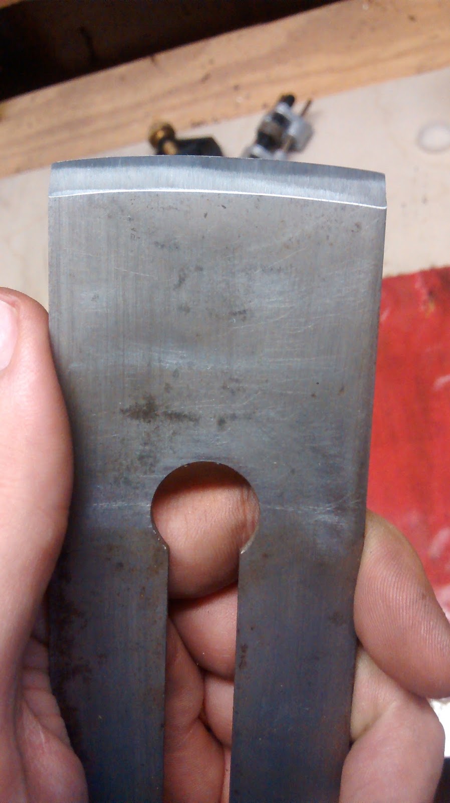
Again not much visible difference except that the blade was previously coated with lacquer or paint to protect it from rust, I guess.

The blade was sharpened with quite a bit of skew. I straightened it out on the grinder.

After flattening and polishing the back of the blade.  There is a bit of pitting, but nothing catastrophic.


The plane sole was in pretty good condition.  I made sure it was flat and shined it up a bit.

The first cut: works like a champ!


You never quite know how good a plane is going to be until you're done tuning it up, but this one turned out really well. Here's the payoff:


Monday, August 22, 2016

A free band saw

Thanks to my wife's keen eye on our neighborhood message board, I just scored a FREE band saw.  It seems that someone was cleaning out their garage and just wanted to get it out of their ASAP.  It's a Craftsman 12" band saw from the 80s.

Check out the pictures below.  It needs one new tire and a new table insert (which I might be able to make myself).  It seems like the bearings are in good shape, the tensioner works, and the motor runs.  So after some cleaning, lubricating, adjusting, and $30-40 in parts it should be in good shape again.

This is after I brushed off the loose dirt and cobwebs

It's dirty, a little rusty, and several generations of
wasps have lived in there, but the bones looks
pretty good.

The motor pulley and belt need to be re-attached.  No biggie.

This is probably the biggest issue (which still isn't bad).  The
top wheel needs a new tire since a section of it is missing.

Monday, August 15, 2016

Sharpening old tools

If you thought, based on the title of this post, that I'd be discussing refreshing some previously learned skills, you may be disappointed.  Instead I'll actually be showing off how I sharpened some vintage woodworking tools.

I've recently been re-discovering my woodworking hobby, while learning to use hand tools in place of the power tools I've previously used.  There are many reasons I've decided to use less electricity to make wooden objects, but I'll save all of that for another post.  I'll just focus on sharpening for now.

Rough Grinding
Usually you start sharpening by rough grinding the bevel angle on the blade.  This step is only required if you are setting a new bevel angle or if the blade is otherwise damaged.  You can do the rough grinding by hand but I opted to use a power grinder with a 40 grit grinding wheel.  So I lose some hand tool merit points for using electricity here.  All of the blades I sharpened were to 25 degrees, which is pretty standard.

Honing Methods
There are tons of ways to sharpen metal blades: oil stones, water stones, diamond plates, etc.  I'll be using a lesser-known method: sand paper.  I learned about using sand paper from the Naked Woodworker, but there are many people that prefer this method, often known by the name Scary Sharp.

The basic requirements are three or four grits of sand paper going from around 150 grit up to 800 or 1000.  Spray adhesive (or similar) is used to attach the sand paper to a flat surface like plate glass.  When I went to the Home Depot to get supplies they only had very thin window glass, and I wanted something thicker.  I was impatient so rather than waiting to go to a glass shop, I looked around in the tile section and found a large floor tile that was dead flat (I checked it with a straight edge).  I haven't heard of anyone using floor tiles before but I can't think of a reason it shouldn't work.

With any of these methods it's common to use a honing guide to keep the angle, though some people like to freehand the bevel angle once it's been rough ground.  I used two different honing guides, an Eclipse and a Veritas.

The Block Plane
The first thing I tried to sharpen was an old Craftsman block plane (circa 1920). It was the first time I've use a grinder and I had a little trouble getting the tool rest set to the right angle.  The end result is that the blade has two bevel angles as you can see in the photo below.  Functionally it works fine, even if it's a little ugly, and after honing I can shave with it.

I tested the plane out by cutting some end grain bevels (something a block plane is ideal for).  It seemed to perform pretty well even while taking a pretty aggressive cut.


The Smoothing Plane and Chisels
Next up was a nice Millers Falls Smoothing Plane.  This one was straight-forward except that whoever had previously sharpened it had kind of messed it up and put quite a bit of skew on the blade (maybe it was intentional).  I ground off the skew and made it straight across again.  I also knocked down the corners of the blade a little to reduce tear out.  After honing I was able to take paper-thin shavings which is what you need in a smoothing plane.

I also sharpened some chisels, but they were brand new and factory ground to 25 degrees to they just required a quick honing.  I didn't even get any pictures of the chisels.


The Jack Plane
I left the most difficult one for last.  A jack plane is usually used for taking off lots of wood quickly.  To optimize for this the blade geometry needs a little curve, which is called camber.  Although the curvature is slight this allows the plane to scoop the wood out and take off much larger chips.  This is really useful if the wood is twisted or cupped and you need to take off an eighth of inch or so.

I wanted to take about a sixteenth of an inch off of each corner, and beyond that I just planned on free-handing it on the grinder. I got a tip from watching some YouTube videos that it easiest to take the corners off by putting the blade into the wheel at 90 degrees and then once the curve is ground the same 25 degrees bevel is established all the way across.  It took a while but I eventually got the camber you can see below.

Honing a cambered blade was a little trickier than a straight blade, since you need to sort of lean the blade back and forth as you hone.  For this I used the eclipse guide since it has a small wheel that lets you lean the guide much easier than the Veritas guide.

To test I took a fairly conservative cut, and although it may be hard to see in the photo below, it took some quite thick chips.  It was interesting that I could feel the camber of the blade in the chips, in that they were quick thick in the middle but got paper thin at the edges.


Saturday, August 13, 2016

LabVIEW for BBB and RPi Internals: Yocto, chroot, and other strange words

I recently helped create a toolkit to allow running LabVIEW VIs on a BeagleBone Black (BBB) or Raspberry Pi 2 (RPi2).  In this post I'd like to get into some of the technical challenges we encountered along the way.

SamK, the author of the LINX toolkit, took over creating the LabVIEW I/O library.  LINX was originally written to allow LabVIEW to easily access the I/O on Arduinos and similar devices, so he naturally chose to use the same LabVIEW API to access I/O on BBB and RPi2.  The underlying implementation on the BBB/RPi2 is fundamentally different than the normal LINX toolkit.  Details on the architecture is available here.  The source code for the library is available here.

Issues encountered
I worked on making the LabVIEW run-time engine work on the BBB/RPi2.  The LV run-time had previously been ported to the ARMv7a CPU architecture and the Linux operating system in order to enable the latest generation of NI's CompactRIO industrial controllers.  This made things way easier but there were still some issues that had to be overcome:
  1. The run-time was already built around the fact that it was running on the an armv7a architecture.  This is fine for the CPU on the BeagleBone Black and the Raspberry Pi 2 and 3.  But the Raspberry Pi 0 and 1 use an older CPU that only supports the armv6 instruction set, so for this reason we decided not to support the older Raspberry Pis.
  2. The LV run-time usually runs on Linux in NI's own embedded Linux distribution, but for the BBB and RPi we wanted to make LabVIEW run on the recommended Linux distro for each of these targets which happens to be debian based.
  3. The ARM Linux versions of the LabVIEW run-time and the rest of the NI software stack are compiled with the softfp gcc flag, while most ARM Linux distros use the hardfp flag.  Binaries built with one flag are incompatible with binaries built with the other.  These means that the LabVIEW run-time cannot use the hardfp libc that is present on Raspbian.  That's a problem.
Solutions found
The first issue is kind of a limitation of the CPU in the Raspberry 1 and since most people are using the
newer Raspberry Pi 2 or 3, we decided that the easiest way to resolve the issue was to not support the RPi 1.  I know it kind of sucks for people that want to use the RPi1 they have lying in a drawer somewhere but considering how cheap RPi's are in general, it doesn't seem like such a big deal.

To solve the rest of the issues, I decided to use a Linux chroot.  At it's core, a chroot, or root jail, runs a process with a different root directory.  That's really all there is to it, but the implications are pretty far reaching.  When a process runs it loads its libraries from the /lib directory among others, so if we provide a softfp set of libraries in a different directory and chroot the LabVIEW process to that directory then we can solve issue 3.  And if, also in that same chroot directory, we provide a simple Linux distro that is custom-tailored to LabVIEW, then we can solve issue 2.

Building chroots in Yocto
To make this little chroot Linux distro, I used the Yocto project, which I was already familiar with because I use it at work on a daily basis.  I created a Yocto layer that has everything needed to create chroot.  The image recipe includes the LabVIEW run-time engine and the VISA and LINX I/O libraries.

Installing the chroot
With the chroot image created, I needed some way to install it on a target.  Since both the BBB and RPi use Debian-based Linux distros I create a deb package installer.  The install includes the chroot image created using Yocto, a systemd unit file to start the chroot and LabVIEW run-time at boot, a dependency to the schroot utility, and a small daemon that I'll discuss below.

Emulating the NI System Web Server
On traditional NI Linux RT targets, there is a system web server which provides various system configuration services like changing the network settings.  We don't support most of these system configuration services, but we do need to support restarting the LabVIEW run-time.  This is needed because when deploying a LabVIEW startup app to the target, the run-time needs to be restarted.

Since we only needed this service, rather than skimming though the significant codebase of the System Web Server, I instead took the tact of reverse-engineering the reboot web service using Wireshark.  Basically, I ran a Wireshark capture while remotely restarting a traditional LabVIEW Real-Time target.  This worked far better than I would have guessed, and soon I had a small script which implements a small subset of the NI System Web Server's functionality.  I created another systemd unit file to start the script at boot time and put it all into the debian installer.

Security
On important note is that the NI System Web Server does lots of work to ensure that all of it's operations are handled securely, but for my quick-and-dirty python script I did not implement any of these security features.  The LabVIEW run-time is also run as the root user so that it has access to the I/O resources that it needs.  On other LabVIEW Real-Time targets, and on Linux systems in general, daemons like the LabVIEW run-time do not run as root due to security concerns.

The implications of these choices is that anyone with access to your local network can restart the LabVIEW daemon remotely, and can run VIs on the BBB/RPi2.  This probably isn't a big deal if your network is private and has a firewall between it and the rest of the Internet, but it's still something to be aware of.


Thursday, June 09, 2016

Introducing LabVIEW support for Raspberry Pi 2 and BeagleBone Black

For the last 6 months, a friend and I have been working on a really cool project, and now I can finally talk about it.

We've always wanted a way to use LabVIEW to program the amazing Linux-based maker devices like the Raspberry Pi and BeagleBone Black.  It seems like a natural fit for programmers that are new to distributed programming, embedded devices, and Linux.  LabVIEW has been an excellent way to write, debug, and deploy embedded applications over a network with the LabVIEW Real-Time module.

So we set out to port the LabVIEW Real-Time module to the BBB and RPi2.  Mainly this consisted of getting the LabVIEW run-time engine running on the BBB/RPi2 and writing some kind of I/O library to make it easy to do things like reading and writing digital lines, reading analog inputs, and communicating on I2C and SPI buses.

In the end, we got it all working and released it to the public, and it's actually affordable as well ($50 + cost of hardware).  All you need is a copy of LabVIEW 2014, the (free) LINX toolkit, and a BeagleBone Black or Raspberry Pi 2 or 3. See this link for more info.

We also spent some time putting together some respectable tutorials to help people get started.

What will you do with LabVIEW on a BBB or RPi?  I'm looking at automating the beer making process, and I've got some friends that want to use it with rockets and robots and other interesting things...


Sunday, March 20, 2016

Creating a customized image for BeagleBone Black or Raspberry Pi

Recently I wanted to create a customized image for a Raspberry Pi.  Basically, I just wanted to download a stock Raspbian image, install some software, change a few configuration settings, and then put it back together just as I'd gotten from the original image.

This is (or should be) pretty simple but I had trouble finding concise instructions for doing it.  What I found fell into one of two categories: 1) instructions for backing up an image, or 2) really complex instructions for generating an image from scratch.

At first glance the backup instructions (like these) seemed perfect.  You run the equivalent of Linux's dd command and end up with an image file that can be flashed to an SD card on Windows, Linux, or Mac.  Perfect, right?  Maybe not.  Here's a scenario I ran into:  I downloaded an image that would fit on a 4GB SD card, I flashed it on an 8GB card because that's what I had lying around, made my modifications, and created a backup image.  The problem was the image is an image of an 8GB card, so it will no longer fit on a 4GB SD card even though the amount of actual data on the card should allow it to live on a 4GB card.

So here is a process that gives us the ease of the backup process, but with the power to resize things back to the original image size:
  1. Download the latest official image for Raspberry Pi or BeagleBone Black.
  2. Extract the image, flash it, and boot it.
  3. Make whatever changes you want to the image (install software, change configurations, etc.).  Keep all other settings to the defaults, like the hostname, users, and passwords.
  4. Shutdown the target, extract the SD card, and backup the image using one of the methods here.
  5. This will backup the entire SD card, and will likely create an image that will be much too large.  You can shave off the extra unallocated space (basically restore it back to the same size as the stock image download from Step 1), using the steps in the "Shaving the Image" section of this document.
  6. Zip up the finished img file.

Thursday, March 17, 2016

Controlling flow through a wort chiller, part 2

Continuing my series of posts with boring-sounding names, I've got more results from my wort chiller pump.  Last time I was trying to control the flow through the wort chiller such that I can ensure that hot wort gets cooled to a reasonable temperature by the time it leaves the chiller.

To that end, I made a series of flow restrictors, which are just some smaller diameter tubes I could insert in the tube between the chiller and the fermenter vessel.

Flow Restrictors
I made the restrictors out of some wooden dowel rods I had lying around.  Yes, I know that wood is one of the worst materials I could have used for this purpose since it's porous, and therefore could leak air and water and be a wonderful home to unwanted bacteria.  I started with wood because I already had it on hand and I'm a woodworker so I'm better equipped to machine something out of wood. So if the experiment works I'll definitely be re-making the restrictor tube out of metal or food-safe plastic.

To start making the restrictors I found a dowel rod that would fit snugly in the 1/4" ID hose I was using, which I think ended being a 3/8" dowel.  I cut a bunch of 2 inch lengths of dowel and then picked 3 diameters I wanted to try first: 1/8", 3/32", and 1/16".  I clamped each rod in a wooden clamp, checked that it was perpendicular, and used my drill press to drill straight through the center of the dowel.  After that I checked each rod into the drill press and used a file to taper the ends so it would insert into the tubing more easily.  They ended up coming out pretty well, but not perfectly centered which should be fine for this experiment.


Measuring Initial Air Evacuation
Before I got to testing my new flow restrictors I wanted to investigate the initial start of the pumping process.  I suspected that it would take some amount of time to evacuate most of the air from the system before the liquid would start flowing.  To test this I used my usual volume of 16oz. of water to pump, but before the container was empty I poured in another 16 oz. of liquid.  By timing both a 16 oz. and 32 oz. sample, and subtracting the difference between them I should be able to get an idea of the amount of time required to evacuate the air.

For this test I ran the pump full speed at 5 volts.  Here are my results:
16 oz. water0m 41s
32 oz. water1m 06s
delta0m 25s
air evac time0m 16s

Breaking the results down a bit, this means that the time to transfer 16 oz. of water is really about 25 seconds and it takes 16 seconds to remove most of the air from the inside of the pump apparatus.  For the following tests I won't be adjusting for this initialization period, but it's something good to keep in mind.

Full-speed Flow Measurement
For the next round of tests, I kept the pump on full speed at 5 volts for the full duration of time it took to transfer 16 oz. of water.  As you can see in the picture below, I inserted the flow restrictor in the hose that connects the output of the graham condenser to the input of the fermenting vessel.

Here are my results:
restrictor size16 oz. transfer time
none0m 41s
1/8"0m 47s
3/32"1m 02s
1/16"3m 20s

It seems that the restrictors are working though their effect is definitely non-linear.


Modulating the Pump Motor
Next I wanted to try to introduce another variable into the equation, which is to vary the on-time of the pump.  In other circumstances I would use pulse-width modulation to allow a microcontrollers (like an Arduino) to control the motor, but for now I don't want to mess with setting up the motor drive circuitry.  So I'm going to do "human powered" pulse width modulation and just turn the pump motor on and off in terms of seconds.

Here are the patterns I came up with:
pattern numinit periodrepeating pattern
10s10s on, 10s off
220s10s off, 10s on
30s20s on, 20s off
410s10s off, 5s on
510s10s off, 3s on
610s10s off, 2s on

Each pattern has an (optional) init period where the pump is on, with the goal of initially evacuating the air from the system.  After the init period, each pattern has a repeating pattern with the goal of replicating the duty cycle and period based control used in pulse width modulation.

I ran these patterns using the 3/32" restrictor since this restrictor seemed to give the best balance of hole size vs. flow restriction.  I want to keep the hole size as large as possible because I'm concerned that if the hole is too small it will get clogged when I run actual wort through it.

Here are my results with the 3/32" restrictor:
pattern num16 oz. transfer time
11m 14s
21m 11s
31m 12s
41m 21s
51m 33s
62m 46s

So it seems that my simplistic pump motor modulation is working, at least enough to proceed.  I could have tried a pattern with an even shorter on time than pattern 6, but a 2s on time was about the shortest amount of time that I could consistently maintain over over the course of several minutes.

It's worth noting that by the end of my test runs the 3/32" restrictor was allowing a small amount of outside air to be pulled inside the tubing.  I think this may change the results slightly, but I don't think it would have changed things enough to alter my conclusion that the strategy seems viable.

Conclusions and Future Work
The results from using a restrictor while modulating the vacuum pump seems to show enough promise to proceed.  If you multiply out the time to transfer 16 oz. of water with around a 20% duty cycle, it would probably take around 24 minutes to transfer a gallon of wort through the chiller which seems like it should be sufficient to chill down to room temperature.

My next steps are to get my test rig ready to pump some near-boiling water though it, make a 3/32" restrictor out of something more durable than wood, and add some automation to control the vacuum pump motor.


Thursday, January 21, 2016

Controlling flow through a wort chiller, part 1

Now it's time to start putting together my last two experiments in order to control how quickly the wort flows through the chiller.  This will hopefully allow me to control how quickly and efficiently the wort is chilled.


I've added a stainless steel racking cane as an input tube to the condenser tube.  The condenser tube is now better supported with a ring clamp that allows me to keep tube properly supported at an adjustable angle. The tube that leads into the glass jug is just the right diameter to fit snugly in the output of the condenser tube.

As part of this I also want to try and slow down the flow of water through the condenser tube.  I took a simple approach of using a pinch clamp to see how much that restricts the flow.  I then pulled 16 ounces of water and timed how long it took on a stop watch.

table of data
clamp gap(cm) transfer time(s)
open 0:38
0.5 0:38
0.4 0:38
0.35 0:41

Based on the numbers I collected, it seems that the pinch clamp is effectively binary, all off or all on.

Since the pinch clamp didn't work very well, I'm going to try inlining a smaller tube to see if that restricts the flow better.