I created a demo recently to show off the security node I've been working on implementing using JeeNodes. This is not the final version (though the hardware is pretty close to final), eventually I want to use something like HouseAgent to control the entire system.
Hardware
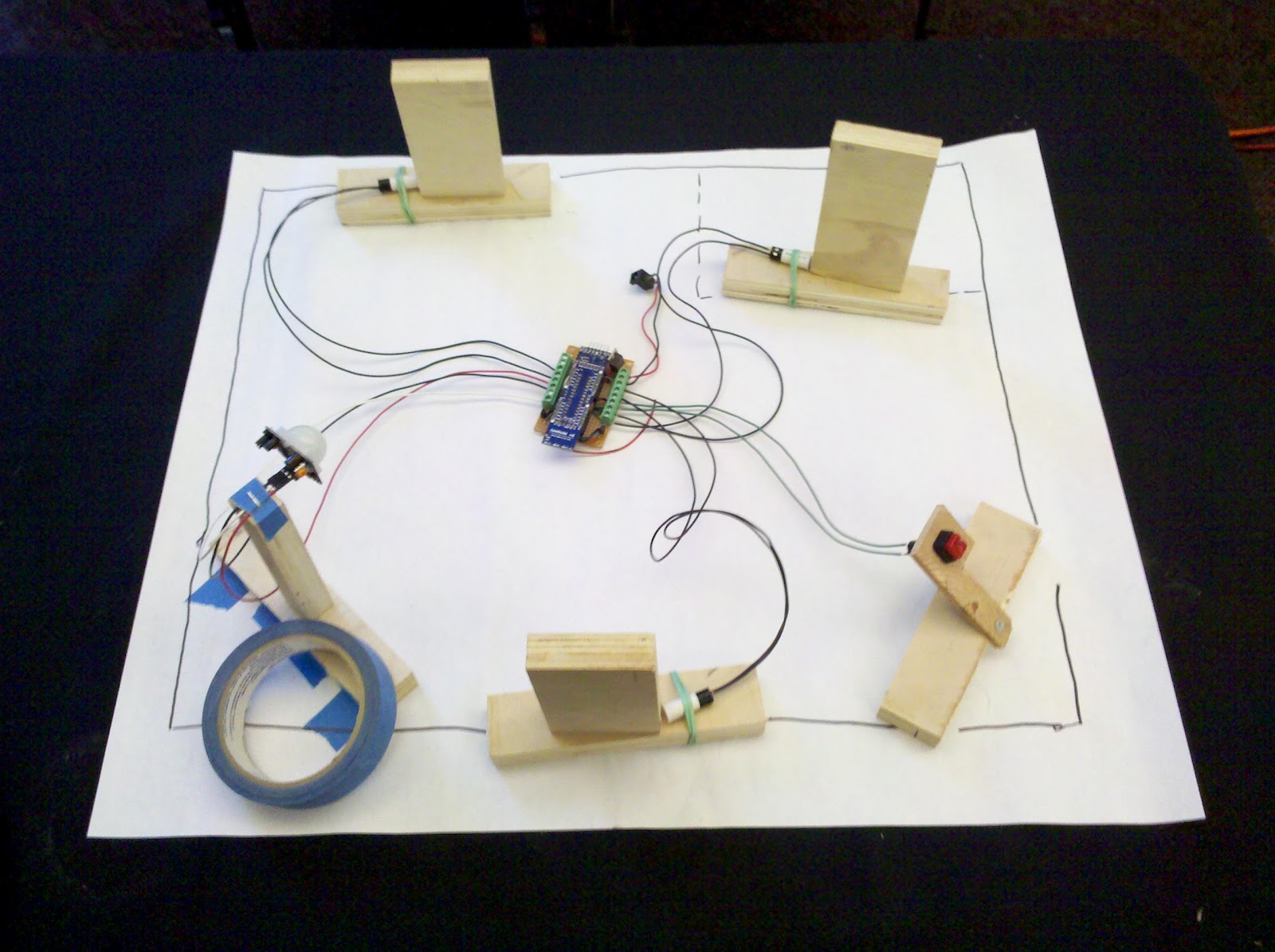 |
| Very rough model of my house with simulated doors, panic button, and motion sensor. The JeeNode is in the center. |
I decided to use this project as an excuse to try out Fritzing. I primarily wanted to try this since I thought it might be a decent tool to use to lay out the components on the protoboard, since I usually use EagleCAD but it doesn't allow you to work with protoboard. The breadboard view in Fritzing worked well for this but I still think I could have done it more quickly with pencil and paper. But at least now I have a decent (if messy) electronic version.
The interface is simple. The switches are wired directly to the digital inputs of the various JeeNode ports (also using some of the unused analog inputs as digital inputs). I use the ATMega328's internal pull-up resistors to save some components in the schematic. I used a 7805 voltage regulator to bring the 12 volt supply's voltage down to something more reasonable for the JeeNode. The 5V is regulated further to 3.3V by the JeeNode's on-board regulator.
I added a couple of transistors to the circuit to control power to the motion sensor and siren which both use 12 volts. I also inserted a switch in the siren circuit so there's a hardware way to turn the siren off just in case there is a software failure (the siren is REALLY loud). While I'm testing things out I'll probably only have the siren circuit enabled while I'm home so I can monitor things.
The firmware is pretty simple and has lots of room for improvement. It should be noted that I haven't done any work to improve the power usage of the firmware since this node will be wall-powered (the motion sensor and siren require way too much power to be battery powered). The sketch polls all of the inputs every 2 seconds and sends out a packet with the sensor readings. It also checks for received packets that contain one of two commands: to power up/down the motion sensor or to turn on/off the siren.
In the near future I will probably make this sketch event-based; it will only send sensor packets when one of the inputs changes value (or once when the node first powers up. I'll also probably make it handle a 3rd command to poll all of the inputs and return a packet with the data (force an event). Since this node will always be wall-powered I probably won't bother with using the power management functions available in JeeLib.
Host Software
I wrote the host software in LabVIEW. This is a prototype and will eventually be re-written to be a web-based interface (perhaps using HouseAgent). The VI monitors the serial port for messages from a gateway JeeNode running the standard RF12demo sketch. It then parses these messages and extracts the sensor value from them. Based on pressing buttons on the front panel the VI will also send messages to the node to turn on power to the motion sensor; it then starts a timeout to allow the motion sensor time to initialize after power up.
I used Sketchup to create a quick, not-to-scale, 3D floor plan of the first floor of my house. I think it spruces up the front panel nicely.
 |
| Screenshot of the host-side UI |
 |
| The host including the host-side JeeNode connected via USB |
10 comments:
Very cool thanks for sharing!
What do you think the length of the sensor wires could be? I recently wired my house for CAT5 using a single cable to dual ports (http://www.cabling-design.com/references/pinouts/split.shtml) so I figured I could tap into the second network connection or run a separate CAT5 as I have plenty of extra.
Zoso1: Without getting into too many calculations, the answer is "very long". Since these are digital sensors the worry is that the resistance of the sensor leads would prevent the JeeNode from sensing the state of the sensor correctly. I've been using the internal pullup resistors of the ATMega328 chip, which have a value of 20K ohms. When the sensor is "open" the pullup makes the JeeNode see a logic '1' or high voltage. When the sensor closes the idea is that it should pull the digital input down to 0 volts so the JeeNode sees a logic '0'. What we need to worry about is that if the resistance of the sensor wires becomes a significant portion of the pullup resistor value (5-10K ohms or more) then we've created a voltage divider when the sensor closes and the JeeNode will still see it as a logic '1' when the sensor is closed. But to get the sensor wires up to the kilo-ohm range would require very long wires. To give you an idea, according to wikipedia a 1 meter length of 1mm diameter copper is only 0.02 ohms. Hope that helps.
Can you be able to compile a version the vi's for labview 2010 or lower
Leadfeet123, I can save a version for you in LV 2010. I don't want to put it up on github because I'd have to ditch the more modern UI controls present in 2011 and for some reason the size of the VIs blows up to several megabytes in size. If you can give me an email address to send it to I'll make a copy just for you.
Hi there,
I am building a similar thing on an Arduino. I am fairly new to microcontrollers and electronics (but on a steep learning curve ;-)) ), so I wanted to ask you for some advice. I am using a loudspeaker / siren (it says 8 Ohm on it) salvaged from an actual outdoor alarm siren. The unit has a 12V lead battery as backup for power faliures. Therefore I assume that it can be powered by 12 V. My solution is a power Mosfet triggered by the 5V/low current from the Arduino which switches on the 12V from the battery (acutally the MOSFET is "behind" the siren "opening" the way to Ground). I naively assumed the siren sounds when connecting the siren to 12V, however, you only hear a "BLIP" sound and not a continuous one. Browsing through some blog and forum posts around electronics, I then figured that the siren/loudspeaker needs some kind of "wave" signal or frequent on/off switching (sorry for not using the right (newbie) terminology). In fact, when trying that on a PWR pin, which does some switching on and off at a certain frequency I actually get a continuous tone. The sound however is not very loud. My question is now twofold. Any advice on what I could do in order to increase the loudness? E.g "tweaking" the PWR characteristics? its frequency? (I am assuming that the MOSFET provides a decent current like at least 1 Amp). Otherwise, I read that you write "... the siren is really loud": what are you using in terms of horn/loudspeaker/buzzer, and how is it interfaced with the microcontroller (voltagem, amps, digital/analouge/PWR)? any advise is much appreaciated!
Hi hobie,
I'm guessing from your post that you've got a bare speaker. The siren I'm using actually has some driver circuitry around it to drive a tone to the speaker and properly amplify it. I'm not really an expert on audio amplifier circuits but here is a forum post on driving an 8 ohm speaker from an arduino. I hope that can get you started.
Post a Comment